The gas recovery test of respiratory chambers
Anne Louise Frydendahl Hellwing 2
Peter Lund 3
Michael Derno 4
Björn Kuhla 1
Marcel Heetkamp 5
Gemma Miller 6
David Humphries 7
Frédéric Anglard 8
Yvanne Rochette 8
Cécile Martin 9
Tom Gardiner 10
Marc Coleman 10
1 Leibniz Institute for Farm Animal Biology (FBN), Dummerstorf, Deutschland
2 Aarhus University, Tjele, Denmark
3 Aarhus University, Tjele, Dänemark
4 Leibniz Institute for Farm Animal Biology (FBN), Dummerstorf, Germany
5 Wageningen University & Research, Wageningen, Niederlande
6 Scotland's Rural College, Dumfries, Vereinigtes Königreich
7 University of Reading, Reading, Vereinigtes Königreich
8 Université Clermont Auvergne, INRAE, Saint-Genès-Champanelle, France
9 Université Clermont Auvergne, INRAE, Saint-Genès-Champanelle, Frankreich
10 National Physical Laboratory, Teddington, Vereinigtes Königreich
Keywords
leakage, mass flow, span gas, correction, diffusionIntroduction
Respiratory Chambers (RCs) were originally constructed with the purpose to study heat production from animals by quantifying oxygen (O2) consumption and carbon dioxide (CO2) production (initially detailed in the 18th century by Lavoisier and Leplace; for the history of calorimetry, see McLean and Tobin [1]. Enteric methane (CH4) is measured in calorimetry studies, as CH4 is an energy loss [2], [3]. The RC can therefore be used to quantify the CH4 production from animals, and many new RC units have been constructed during the last decades with the main aim of measuring CH4. The constructed RCs in research institutes differ in the design or material; however, their principles remain relatively similar. There are both hypobaric (= pull type) and hyperbaric (= push type) RCs, respectively, controlling air pressure below and above atmospheric pressure, depending on the position of the pumping system [4]. The majority of chambers is designed so that the air is sucked through the chamber (pull type/under-pressure), which requires more effort in terms of maintenance and calibration requirement for the gas meters than in push-type systems, where dust and NH3 loads are much less abundant. For all types of chambers, continuous measuring of all gasses of outside air content is essential as there might be contaminant levels, which should not be neglected. A recent ring-test study in the UK revealed that different RC installments are at risk of producing data that is of poorer accuracy than is ideally required [5]. This risk can be avoided through adoption of appropriate calibration regimes for all sensors within a RC system. Finally, proper validation of chambers is necessary for better comparison of gas production from cattle between facilities. Although calibration of different compartments of the RC is essential, particularly in identifying the source of errors, validating the whole system is without a doubt the most crucial of all in establishing the overall performance assessment. A set of tests needs to be established and implemented in order to identify and quantify different systemic and random uncertainties of the RC system. Knowledge about these types of uncertainties is vital for rapid elimination or appropriate correction of data, which in turn improves the accuracy of the gas exchange measurement.
The gas recovery tests, for assessing the performance of the whole RC system, can be conducted via different approaches such as continuous gas injection of CO2 or CH4 directly into the closed open-circuit chamber. The ducting efficiency can also be determined by injecting test gas only into the gas extraction pipework without releasing it in the chamber. Gerrits et al. [6] urged researchers to conduct routine gas recovery tests of their RC and to provide the results of the recovery in publication. We believe that a universally acceptable protocol for RC validation ought to be implemented, which would allow a more realistic comparison between the data acquired by RC systems from different research infrastructures. The following guideline has been written with the intention to generate accurate and comparable data from different European research units. This could eventually pave the way for improving our knowledge on energy metabolism and GHG emissions from cattle.
Prerequisites
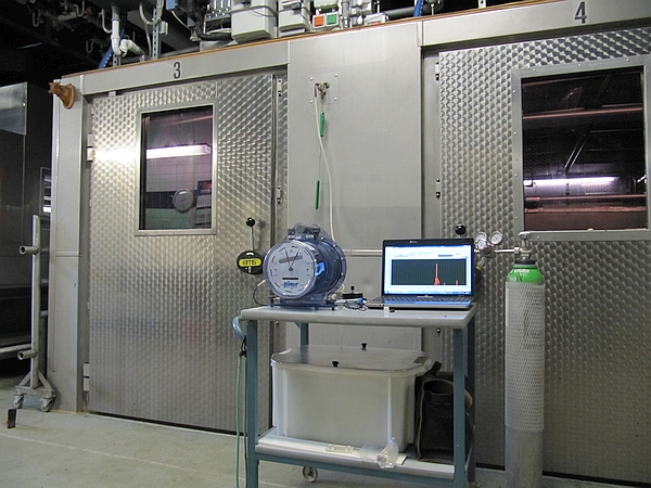
The purpose of the present guideline is to provide the key steps on conducting the gas recovery test of RCs. The operator shall consider a number of mandatory materials such as a) weighting balances or gas flow meters; b) CO2 or CH4 gas cylinders with high purity and c) connecting tubing, which are necessary for conducting a gas recovery test (Figure 1). Moreover, prior to the gas recovery test, all gas sensors and flow meters shall be calibrated and, if necessary, cleaned either by a certified laboratory or in-house on regular bases (see the guideline on Respiratory chamber within this chapter). In addition, a leak tolerance test can be useful to point out chamber leakage problems [4]. The results of the gas recovery test merely provide a quality check that the RC results are within appropriate limits when compared to a reference emission. The Animal Trail Ontology for Livestock (ATOL) number linked with this guideline is: ATOL_0001390 (for complete list of ATOL, please visit https://www.atol-ontology.com/en/erter-2/).
A – Conducting the gas recovery test
- The gas recovery test of RC facility shall be carried out under conditions as close as possible to those present during typical chamber use (e.g. if animals are present in the same barn as the RC facility during typical use then anmials should also be present when the gas recovery tests are being performed).
- The gas recovery test of RC systems shall be performed before and after a new experiment. In case of longer-lasting studies (over months), it is also recommended to plan gas recovery tests in between to confirm continued satisfactory operation.
- If the flow system or gas analyzers of the RC (or any part of the chamber) need to be changed or altered in a way that could affect experimental results, an immediate gas recovery test prior to any new experiment shall be carried out.
- The recovery test shall be conducted using a high purity reference gas (≧99.9%). The amount of injected gas (CH4 or CO2) shall be determined by measuring the mass or mass-flow of gas released into the RC using calibrated instruments to an uncertainty of ≦10%, k=2 (coverage factor), of the recovery test performance target. In case a definite volume of test gas is released into the chamber, the temperature, pressure and humidity has to be recorded to allow the conversion into mass. (NOTE: For the recovery test to be a valid test, it is necessary to be able to measure the gas released to an uncertainty significantly better than the performance target. For example, if 800 g of CH4 are released in a gas recovery test, the performace requirement of 3% [97–103%] equates to a mass of 24 g. Hence, for the test to be valid, it must be possible to measure this mass to an uncertainty significantly better than ±24 g. Consequently, to comply with this guidance document, the operator is required to demonstrate that the mass loss can be measured to an uncertainty of no greater than ±2.4 g at k=2, i.e. 10% of the recovery test performance target).
- The operator should inject such an amount of test gas into the chamber to achieve gas concentrations comparable to those measured during an animal experiment. Depending on the structure and size of the RC, the type of flow meter and type of test gas in use, the duration of the gas recovery test differs from one installment to another. (NOTE: it can minimise some potential issues if as much of the gas delivery system as possible is placed within the chamber. For example, if components of the apparatus leak but are within the chamber, then this mitigates the risk of a biassed test result. Also, the operator should ensure the test time duration is sufficient to obtain a mass loss large enough to enable compliance with the uncertainty given in clause A4 above).
- The recovery rate (%) is obtained as: \(\small 100 \times \text {mass(Gas)}_\text{measured} \over \small \text{mass(Gas)}_\text{injected}\). The recovery should preferably be between 97–103%. If the the test result is outside this range, the system should be controlled for errors (see section B) and corrected if possible (see section B). The recovery test should then be re-run. The documentation of the results of the recovery tests as a log is recommended to allow examination of long-term stabilitiy, success of correction of defects or drifts of the recovery.
- The authors shall clearly state the recently obtained recovery rates including the number of tests, mean and standard deviation, and the used gasses, when publishing the outcome of any RC experiment.
- The results of any RC experiment shall be preferably published as data uncorrected by the recovery rate to allow for direct use in, e.g., latter meta-analyses approches. In case that the results of the recovery test were used to correct experimental data of an RC experiment, the reason and mathematical way of correction shall be explicitly stated. Also, the operators shall declare if this guidance document has been followed, and – if only partly followed – state the deviation and the justification for the deviation.
B – Troubleshooting upon a failed gas recovery test
The authors would like to stress the fact that this section is entirely dedicated to proposing some approaches, in case the gas recovery test of the particular RC does not meet the recovery test performance target as given in section A. The following provides a non-exhaustive list of potential sources of recovery failure, and therefore issues that could be considered in the event of a failed recovery test. Of course, the following points will remain as suggestions/recommendations for the operatives, until they will be further evaluated and validated.
- If a gas recovery test is failed, repeat the gas recovery test a further 3 times. If the performance target is met on all 3 repeat tests, then the original test can be considered an outlier and the chamber is compliant with the requirements of this guidance document.
- If the failed recovery test is repeatable then this indicates a high degree of certainty that there is a real issue with the chamber and some remedial action is needed. It is recommended that the operator first attempts to locate the cause. The diagnostic procedure described below provides method to facilitate such an investigation.
- Gas release validity: Could the outside of the cylinder have gained or lost matter? I.e. could foreign material have been picked up when moving the cylinder out of the chamber giving an artificially high post-release mass? If a high release flow rate was used, was any condensation on the cylinder or its pressure regulator observed? Was the cylinder paint scratched during handling? Was the scale calibrated / checked with standard weights before and after the test? These issues and others could add to the uncertainty of the mass measurement.
If the gas release was controlled by flow instead of mass loss, was the mass flow controller calibration within date? Was the mass flow controller given sufficient time to reach operating temperature? Was the back pressure at the input to the mass flow controller set to the correct value? Could the regulator have been providing an inconsistent back pressure (can be tested by trying a different regulator)? Was the mass flow controller used towards the lower end of its range? (NOTE: Generally, the flow uncertainty is an absolute value and so the relative uncertainty increases as the flow rate decreases, i.e., ideally mass flow controllers should always be operated towards the upper end of their range. Using a higher flow rate or acquiring a lower rated mass flow controller are possible solutions). - Test alternative chamber: It is unlikely that an issue will have occurred in all chambers in a RC facility simultaneously. Hence, carry out a recovery test in another chamber having the same gas analysis system. If the test is passed, this confirms that any shared ducting, analysers, and the performance of the recovery test itself, are not the cause of the original failed test. If this is the case, then the issue is located within the chamber itself; if not, proceed to points (3) to (4).
- Analyser(s): Pass zero and span gas through the analyser(s) once more. Is there any evidence of analyser(s) drift across the recovery test? Also, review the pre-recovery test span of the analyser(s). Did the measurement of the span gas give an unusually low reading requiring upward adjustment? This could indicate a leak into the analyser that is diluting samples. Similarly, if there is an O2 analyser and the zero gas is N2 this should read zero, if not, this indicates lab air is leaking into the internal pipework of the analyser(s).
- Analyser sampling line: If possible, inject span gas at the point where the analyser takes sample from the RC output duct. This will confirm integrity of the analyser sampling line.
- Ducting: If possible, carry out a recovery test releasing gas directly into the output duct from the RC, i.e. eliminate the influence of the chamber. If the recovery test performance target is met, this indicates that the ducting is most likely leak free and that the flow measurement (assuming the flow measurement sensor is positioned on the output duct, this is not always the case) is not the cause of the failed test. In most cases, the above diagnostic procedure will isolate where in the respiration facility infrastructure the issue lies, and hence the corrective action needed will be clear to the operator. To provide further guidance, there is below a non-exhaustive list of issues the operator should consider.
- Analyser purge time: Frequently a single analyser is cycled between several chambers in addition to intake air (for a background measurement). At the valve where the analyser switches between chambers connect zero and span gas and determine when switching from zero to span the T90 response time (the time lapse between switching and reaching 90% of the final stable reading). For a previous measurement to not affect the next by more than 0.1% no readings should be taken within the 3 × T90 time interval. If this is not the case, then the measurements may not be truly independent and there may be bias.
- Analyser linearity: A zero and span approach to analyser calibration assumes near perfect linear performance of the analyser. Any non-linearity risks creating a bias unless the concentration observed during recovery tests (or indeed ruminant animal emission measurement) and that of the span cylinder are near identical (which for both is unlikely). To test for linearity pass through the analyser a series of gas standards covering (at approximately equal concentration increments) the concentration range typically observed (a minimum of 5 concentrations are recommended). Given the performance target for gas recovery tests is 3% (97–103%), any deviation observed must be well below this to avoid significant bias. If not, zero and span calibration of the analyser may not be valid and a multi-point calibration regime may need to be adopted by the facility. (NOTE: Regardless of recovery test results, it is recommended that analyser linearity is tested in any case given that ruminant animal emission measurements will vary across the analyser’s concentration range. This will show if a zero and span calibration approach is valid or if a multi-point approach should be adopted).
- Flow meter positioning: Ideally, at the point where the flow is measured, the direction of the flow will be parallel to the duct and there will be no off-axis components. However, this is not always the case as upstream elbows and joins can cause the flow to swirl. Traversing the flow monitor across the duct diameter will show the homogeneity of the flow profile and confirm (or otherwise) the appropriate positioning. (NOTE: there are available swirl independent flow meters and meters which are not point meters and therefore measure the total flow. These could be considered in the design stage/upgrade of chamber facilities).
- Ancillary sensors: Often temperature, humidity and oxygen concentration are also measured as part of quantifying ruminant animal emissions. Are the calibrations of these sensors in date? If they are intercompared to sensors from another chamber is the level of agreement the same as what has been observed previously? Are the readings from these sensors what would be typically expected or do any data appear erroneous?
- Air density correction: Carefully consider if correction to STP is required. A key factor is how the flow meter is calibrated, so it may be necessary to consult with the calibration service provider to determine the conditions under which the data are outputted from the monitor.
- Inhomogenous mixing in the chamber: This can be eliminated, or otherwise, by carrying out a series of releases in different locations and demonstrating that there is negligible location dependency. With respect to CO2, this molecule is heavier than air and when released from a cylinder may be at a lower temperature than the chamber atmosphere. Consequently, the CO2 could pool in the chamber and cause a bias in recovery testing. To mitigate this the facility could experiment with positioning a fan in the chamber during CO2 release in order to facilitate mixing. (NOTE: this recommendation is in contradiction to the introductory text to this chapter which states that recovery tests should be carried out under conditions as close as possible to those present during typical chamber use. However, whilst a fan would not be present during ruminant animal emission measurements an exception is justified in this case as ruminants will exhale warm – above ambient temperature – CO2 facilitating mixing and so use of a fan is appropriate in this case).
- Contamination from barn air: If chambers are housed within a barn, and do not take in-take air from within the barn, then the integrity of the chambers can be tested by running them empty. If readings are observed above ambient levels, this indicates that emissions from animals in the barn are ingressing into the chambers. (NOTE: this test assumes chambers are operated at sub-atmospheric pressures).
- Back diffusion-based losses: Some facility designs drawn in in-take air under a gap between the floor and chamber doors. If a release is carried out where the flow rate out of the cylinder is high, the released gas can back diffuse out of the chamber leading to losses. Using a flow control device after the cylinder regulator to control the flow to a rate commensurate with average animal emissions should help to minimise this. (Release of a coloured gas can sometimes visually demonstrate if back-diffusion is an issue).
References
[1] McLean JA, Tobin G. Animal and human calorimetry. Cambridge: Cambridge University Press; 1988.[2] Johnson KA, Johnson DE. Methane emissions from cattle. J Anim Sci. 1995;73(8):2483-92. DOI: 10.2527/1995.7382483x
[3] Goopy JP, Chang C, Tomkins N. A Comparison of Methodologies for Measuring Methane Emissions from Ruminants. In: Rosenstock TS, Rufino MC, Butterbach-Bahl K, Wollenberg L, Richards M, editors. Methods for Measuring Greenhouse Gas Balances and Evaluating Mitigation Options in Smallholder Agriculture. Cham: Springer International Publishing; 2016. p. 97-117.
[4] Heetkamp MJW, Alfernik SJJ, Zandstra T, Hendriks P, van den Brand H, Gerrits W. Design of climate respiration chambers, adjustable to the metabolic mass of subjects. In: Gerrits W, Labussière E, editors. Indirect calorimetry: Techniques, computations and applications. Wageningen Academic Pubishers; 2015. p. 35-56.
[5] Gardiner TD, Coleman MD, Innocenti F, Tompkins J, Connor A, Garnsworthy PC, et al. Determination of the absolute accuracy of UK chamber facilities used in measuring methane emissions from livestock. Measurement. 2015;66:272-9. DOI: 10.1016/j.measurement.2015.02.029
[6] Gerrits W, Labussière E, Dijkstra J, Reynolds C, Metges C, Kuhla B, et al. Letter to the Editor: Recovery test results as a prerequisite for publication of gaseous exchange measurements. J Anim Sci. 2017;95(12):5175. DOI: 10.1093/ansci/95.12.5175